resources
Redundant Power Supply: A/B Rack PDU Feed Mapping and Breaker Sizing
Map server PSUs to A/B rack PDU outlets, breaker banks and upstream sources. Check surviving-feed current, cord requirements and rack power density.
Updated October 2026
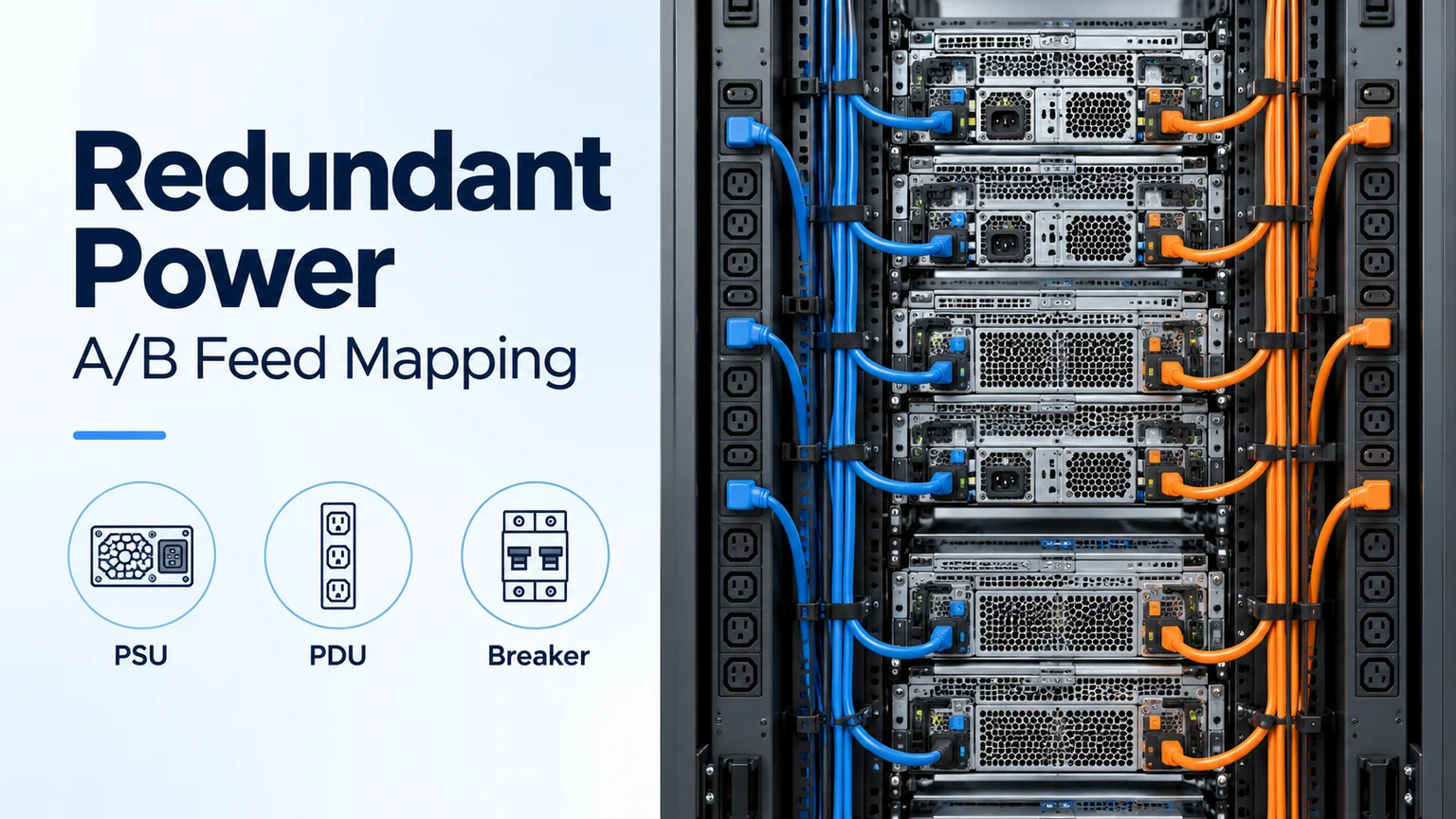
A redundant power supply arrangement keeps a server operating after the specified power failure, provided the surviving PSU modules have enough capacity. For A/B rack PDU feed mapping and breaker sizing, first confirm that the server can survive an entire feed loss, then check the current carried by every surviving outlet bank, line conductor and upstream circuit.
The practical output is a traceable connection map and two separate checks: A lost, B carrying the load; B lost, A carrying the load. This is the review to complete before fixing PDU and server power cord quantities for a rack build or expansion.
| Input | Where to obtain it | Decision it controls |
|---|---|---|
| PSU count, mode and minimum energized modules | Server manual and configured redundancy mode | Whether the intended feed loss is survivable |
| Outlet, bank breaker and line/phase assignment | PDU outlet diagram and physical cord trace | Where current concentrates after a failure |
| Input voltage and permissible continuous current | PDU documentation, breaker setting and installed assembly | The usable capacity of each surviving path |
| Sustained demand and transfer behavior | OEM engineering data and approved commissioning records | Steady loading, transient response and restoration checks |
Confirm what the redundant power supply must survive
Define the failed element before assigning cords. Losing one PSU, one outlet-bank breaker, one rack PDU or one UPS can remove different numbers of power supplies from the same server.
In N+1 module redundancy, N is the number of modules needed to support the configuration, with one additional module available. A 2N, or N+N, arrangement provides two complete capacity groups. The required count and permitted slot grouping come from the server platform and its configured operating mode.
The ASUS RS720A-E13 user manual, section 2.11, requires system consumption to remain below one PSU module's maximum output for its redundant hot-swap mode. It also notes that output varies with input voltage. Check supported DC output capacity at the actual supply conditions; use AC input demand for the facility circuit calculation.
Slot numbering also matters. The NEC Express5800/A1040d family user guide, printed page 187, groups PSU1/PSU2 into channel A and PSU3/PSU4 into channel B. Follow the documented groups for the installed platform rather than assigning alternating slot numbers by habit.
A multi-PSU exception: DGX H100
NVIDIA's DGX SuperPOD: Data Center Design Featuring NVIDIA DGX H100 Systems, Electrical Specifications, requires four of six PSUs energized. Splitting those six modules three-and-three across two feeds leaves only three energized after either feed fails. That arrangement fails the platform's operating requirement.
The guide describes three rack power paths with two PSUs per path. Losing one local path then leaves four energized. Trace those paths upstream as well: in its N+1 arrangement, two rack PDUs share one UPS, so loss of that shared UPS has a larger failure scope than loss of a single rack PDU.
Selection rule: if the proposed outage leaves fewer than the OEM-required modules or insufficient supported output, revise the feed architecture before selecting higher-current PDUs.

Map every server power cord to its upstream source
Use one record per PSU cord, with identifiers that can be checked at both ends. The connection chain is: PSU slot → cord → PDU outlet → protected bank → PDU input → panel circuit → upstream source.
| Map level | Record these fields | Cross-check |
|---|---|---|
| Server and PSU | Rack/node ID, model/configuration, PSU slot, approved module, redundancy mode and minimum energized count | Each failure leaves the required module group and output capacity |
| Cord and outlet | Cord ID/specification, feed group, PDU ID and exact outlet number | Both cord ends match the record and approved connection requirements |
| Protected bank | Bank breaker ID, rating/setting and line-neutral phase or line-line pair | Transfer demand lands on the intended bank and conductors |
| Upstream supply | PDU input voltage/topology, permissible input current, panel circuit and UPS/source ID | Any shared junction is identified and assessed for its full downstream demand |
Label connections with the PDU identity and breaker number; color helps technicians follow the route. NVIDIA's power-connection guidance calls for both source/breaker labels and color coding. A blue cord and an orange cord still need the written map to establish where they terminate.
Phase identity and failure-domain identity answer different questions. Two outlets protected by the same breaker share that breaker failure. Identical phase labels on independent A/B sources can belong to separate circuits. Conversely, different phases supplied by one UPS still share that UPS. Trace the actual protective devices and upstream junctions.
For each server power cord, match the approved equipment connection, PDU outlet, assembly current/voltage rating, destination-market requirements and routed length. Some platforms prescribe the supplied cordset. Use the C13 vs C19 power cord guide for the connector-side decision once the map establishes the required endpoints.

Size breakers for the surviving feed
Use the post-failure continuous load and the installed protection's applicable rating or setting. For the standard North American application described in Eaton's January 2026 application paper AP01200008E:
Minimum breaker rating ≥ 1.25 × continuous current + noncontinuous current
All currents are in amperes for the circuit being assessed. Eaton describes a continuous load as one whose maximum current is expected to persist for three hours or more. Apply the locally adopted requirements and equipment listing when selecting the installation's protection.
For an assembly listed for 100% continuous operation, the same paper gives the sum of continuous and noncontinuous currents without the 1.25 multiplier. That application depends on the complete assembly and the manufacturer's installation conditions, including its enclosure requirements. Conductors, terminations, cordsets, outlets and the PDU retain their own limits.
Use the setting, not just the frame size
Schneider Electric FAQ FA104355 gives a concrete distinction: a 150 A H-frame set to 100 A has a standard continuous-load allowance of 0.80 × 100 A = 80 A. The 150 A frame size is not the calculation base in that setting example.
Record the rating basis beside every limit. If a PDU specification already states its permissible continuous input current, use that figure directly; multiplying it by 80% again would apply a second reduction.
What the balanced A/B planning rule means
For equal-voltage feeds with approximately equal sharing and unchanged load behavior, a useful initial screen is:
Normal current per feed ≤ permitted surviving-feed current ÷ 2
Where an 80% continuous limit applies to the breaker rating, that screen becomes 40% of the breaker rating per feed in normal operation. This is a conditional planning relationship: half of the usable surviving capacity. At equality, the screen leaves no additional growth reserve.
Use explicit transfer-state demand when feeds share unequally, voltages differ, PSU standby modes change the distribution, or loads concentrate on particular banks. Final breaker selection also needs conductor and termination ratings, installation conditions, available fault current and protection coordination.
Check rack power density in both failure states
Rack power density is constrained by the most heavily loaded surviving element. Adding the A and B nameplate capacities does not establish the rack's redundant operating capacity.
For each bank, line conductor, PDU inlet and upstream circuit, record the sustained current in normal operation and after each defined failure. Evaluate the other equipment sharing those circuits as part of the same load record.
| State | Server-side check | Distribution-side check |
|---|---|---|
| Normal operation | Confirm configured PSU mode and actual sharing | Record each bank/line current and identify the controlling limit |
| A feed lost | Identify every de-energized PSU; verify the remaining count, groups and output capacity | Check every affected B bank/line, inlet and upstream circuit at sustained transfer demand |
| B feed lost | Repeat the survival check for the opposite PSU group | Check every affected A bank/line, inlet and upstream circuit independently |
For each element and scenario, calculate:
Continuous-current margin = permitted continuous current − sustained scenario current
A negative margin identifies a capacity failure; zero leaves no continuous-current reserve. Set any additional growth allowance through the project requirements. Correct the limiting bank or path by redistributing compatible connections, reducing load or revising the distribution design, then recalculate both failure states.
A rack-total reading can hide a bank overload. Derive each bank's demand from the outlets actually connected to it. “Double every bank” only works when the transfer distribution justifies that assumption. For three-phase PDUs, check each line current; unused capacity on other phases cannot clear an overloaded conductor. Line-line outlet loads also require the correct topology when translating outlet demand into line current.
Keep the transient check separate. The 80% application allowance is not an instantaneous trip threshold: Schneider's FAQ distinguishes continuous-load application from breaker trip characteristics. Review transfer amplitude and duration, restoration inrush and recovery against the actual time-current curves and platform limits. A positive sustained margin alone does not establish successful ride-through.
For broader monitoring and outlet-selection choices, continue with how to choose a rack PDU for GPU servers.
Validate the map and carry it into the BoM
Acceptance needs a physical trace and an approved failure-state verification. Agree the maintenance window, intended failure boundary, workload, monitoring points and recovery procedure with qualified facilities staff and the server owner before any interruption.

- Match the installed hardware to the map. Confirm PSU slots, approved cords, PDU outlets, bank breakers and upstream circuit labels. Check the actual redundancy mode.
- Establish the loaded baseline. Record the intended workload, supply conditions and bank/line currents. Retain the platform data supporting the expected maximum demand.
- Verify each approved failure scenario. Qualified staff should carry out the platform-specific test plan while the server owner verifies continuity and records PSU status, sustained current and transfer behavior.
- Check restoration. Review reconnection/inrush behavior, alarms and the return to the intended sharing mode. Retain the event traces and breaker settings with the capacity record.
- Freeze the checked map for procurement. Carry exact PDU topology, outlet counts, cord endpoints, rated assemblies, routed lengths and labels into the BoM. Repeat affected checks when hardware or connections change.
The resulting map gives the AI Rack Power Kit requirements a clear basis: the correct accessory lines, allocated to identified outlets and feeds. Keep the map revision with the rack's installation and commissioning records.
Technical references
- ASUS: RS720A-E13 User Manual, V2, section 2.11, “Redundant power supply units” — single-module output limit for redundant mode and input-voltage dependence.
- NEC Corporation: Express5800/A1040d, A2040d, A2020d, A2010d User's Guide, printed page 187 — PSU channel groups and redundancy modes.
- NVIDIA: DGX SuperPOD: Data Center Design Featuring NVIDIA DGX H100 Systems, Electrical Specifications — energized PSU requirements, source topology, labeling and phase balancing.
- Eaton: UL listed 100%-rated molded case circuit breakers, Application Paper AP01200008E, January 2026, pages 1–2 — continuous-load sizing and listed-assembly conditions.
- Schneider Electric: FAQ FA104355, “What is the difference between a 80% rated breaker and a 100% rated breaker?”, modified October 14, 2024 — setting-based continuous allowance and trip-curve distinction.
- Raritan: PDU Circuit Breakers and Branch Circuits: Why Monitor Both? — outlet-bank monitoring and the limits of input-only readings.
Turn your feed map into a PDU RFQ
Send the node PSU count, intended N+1 or N+N redundancy mode, and A/B PDU rated current. Include the server model, input voltage and phase, outlet-bank map, breaker settings, load data and cord requirements.